100% free · Excel
Pipe Pressure Drop Calculator
The calculator from our Instagram reel. Size lines and check pressure drop for steam, water and air using the industry-standard Crane method, right in Excel.
- Up to 30 pipe segments and 10 routes
- Crane TP-410 K-method for fittings and valves
- Steam, water and air properties built in
- ASME B36.10M / B36.19M pipe data
What's inside
Built for piping engineers
Every method and data source is cited in the file, so you can see exactly how each number is calculated.
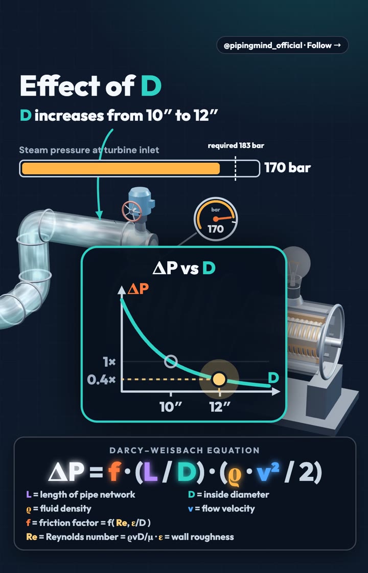
Darcy–Weisbach, done properly
Colebrook–White friction factor solved by iteration, laminar flow handled, and the 2000–4000 Re transition zone flagged.
Fittings by the Crane K-method
Elbows, tees (run and branch), valves, entrances and exits, with K = multiplier × fT of your actual pipe. Reducers and expanders use the Crane formulas.
Fluid properties included
Water and superheated steam from IAPWS-IF97, viscosity from IAPWS 2008, and air as an ideal gas with Sutherland viscosity.
Segments and routes
Build a line segment by segment, carry pressure from one to the next, and total any path through the network as a route.
Elevation and fixed losses
Static head from elevation change, plus fixed pressure drops for filters, flowmeters and control valves from their datasheets.
Warnings you can trust
Checks for velocity and allowable limits, and a warning when a gas or steam segment drops too much pressure for the method to hold.
How to use it
Three steps to your first result
- 1
Split your line into segments
One segment = one pipe size and one flow rate. Start a new one after a tee where the flow changes, or after a reducer.
- 2
Fill the yellow cells
Fluid, flow, pressure, temperature, size, schedule and length, then the quantity of each fitting. Blue cells are drop-down lists.
- 3
Read the results
Pressure drop per segment, route totals and the Summary tab. Check every ⚠ warning before you use a number.
Methods and references
Crane Technical Paper No. 410 · IAPWS-IF97 and IAPWS 2008 · ASME B36.10M, B36.19M and B16.9 · Colebrook (1939), Moody (1944), Swamee & Jain (1976). Pipingmind is not affiliated with or endorsed by Crane Co., IAPWS or ASME.
For preliminary estimates
An educational tool for quick estimates of steady, single-phase flow. It does not cover two-phase flow, slurries, choked flow or transients. Always verify results against your project design basis, codes and vendor data.